中断(一):让 Linux 接收来自 PL 的自定义中断信号
硬件连接
MPSoC 可以接收两组来自 PL 的中断信号。在 Vivado 中,可以通过 PS-PL Configuration -> General -> Interrupts -> PL to PS -> IRQ0/IRQ1 打开。
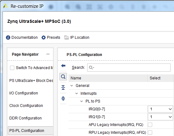
对应的硬件中断号分别是
- PL PS Group 0: 121-128
- PL PS Group 1: 136-143
这两组中断信号既可以与 IPI 中的 IP 的中断信号相连接,也可以和 Verilog 中的逻辑相连接。如果有多个中断源要连接到一组信号中,可以使用concat将多个信号组合成一组信号,然后连接到 IRQ。
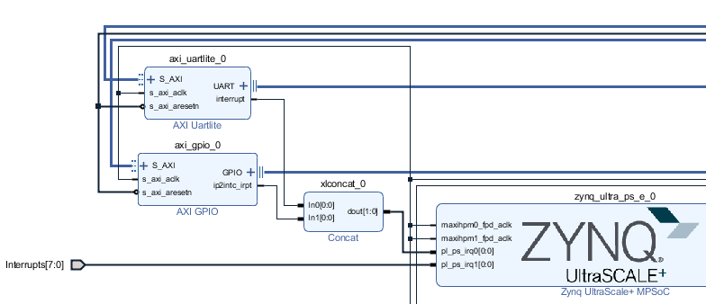
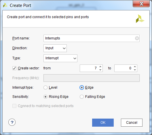
如果要从 Verilog 引入中断信号,需要在 IPI 中按右键选择 Create Port。Port Type 选择为 Interrupt。
软硬件的桥梁: device tree
硬件信息怎样传送给软件系统?
Linux 的答案是 Device Tree。
以下是 Device Tree Generator 为上图中的 AXI UARTLite 自动创建的 device tree。
axi_uartlite_0: serial@a0000000 {
         clocks = <&misc_clk_0>;
         compatible = "xlnx,xps-uartlite-1.00.a";
         current-speed = <115200>;
         device_type = "serial";
         interrupt-parent = <&gic>;
         interrupts = <0 89 1>;
         port-number = <1>;
         reg = <0x0 0xa0000000 0x0 0x10000>;
         xlnx,baudrate = <0x2580>;
         xlnx,data-bits = <0x8>;
         xlnx,odd-parity = <0x0>;
         xlnx,s-axi-aclk-freq-hz-d = "99.999";
         xlnx,use-parity = <0x0>;
      };
创建 Device Tree
Device tree 是纯文本文件,后缀是 .dts 或 .dtsi。当然可以手工从头开始写(似乎没人这么做),Xilinx 也提供了工具来帮助自动生成。
一种方法是使用 PetaLinux,其实这也是 petalinux-build 中的一个步骤。当在一个 PetaLinux 工程中导入 HDF 后,运行 petalinux-build它会自动调用 Device Tree Generator (DTG),为你的工程产生 device tree。用户可以在自动生成的文件的基础上进一步修改,修改的时候注意文件都上会写哪些文件重新生成时会被覆盖,哪些不会。
另一种生成 device tree 的方法是使用 SDK。SDK 可以把 DTG 加载为 BSP Generator,用来生成 device tree. DTG 的下载地址是 [https://github.com/Xilinx/device-tree-xlnx]。下载到本地后,在 SDK 的 Xilinx Tools -> Repositories 中添加解压后的目录。在 SDK 中新建一个 BSP, BSP 类型选择 device_tree
Note: 如果是SDx工具,加载DTG的方法是 Window -> Preference -> Xilinx SDK -> Repositories
Interrupt 属性的定义
Device tree 中和中断相关的属性有两条,interrupts和interrupt-parents。
interrupt-parents指向了中断控制器。在 MPSoC 中有多个外设都有中断控制器属性,分别是 GIC, GPIO, PCIe。
interrupts 后的参数指定了中断号和中断属性。
Device tree bindings interrupts.txt 中定义了 interrupts 后参数的意义。需要注意的是,在中断控制器的属性中有#interrupt-cells的定义,表示interrupts参数需要几个32位的字符。常见的情况是1到3。1个Cell的情况只填写中断号。2个Cell的情况填写中断号和触发条件,GPIO Controller就是这种情况。
ARM GIC 使用的是 3 个 Cell:
- 第一个 cell 是 0 的话表示中断类型:0 for SPI interrupts, 1 for PPI interrupts。PL 到 PS 的中断属于 SPI,所以填写 0。
- 第二个 Cell 表示中断号
- 第三个 Cell 表示中断触发方式。
ARM GIC v3 中断 Cell 说明,来自 arm,gic-v3.txt
  The 1st cell is the interrupt type; 0 for SPI interrupts, 1 for PPI
  interrupts. Other values are reserved for future use.

  The 2nd cell contains the interrupt number for the interrupt type.
  SPI interrupts are in the range [0-987]. PPI interrupts are in the
  range [0-15].

  The 3rd cell is the flags, encoded as follows:
	bits[3:0] trigger type and level flags.
		1 = edge triggered
		4 = level triggered
中断号的确定
Device tree 中 interrupts 的中断号请填写硬件硬件中断号 - 32
中断的驱动程序
PetaLinux 中自带了中断服务程序的例子。
用命令 petalinux-create -t modules -n mymodule就可以创建出例子程序。
其中与注册 IRQ 中断号相关的语句为:
/* Get IRQ for the device */
   r_irq = platform_get_resource(pdev, IORESOURCE_IRQ, 0);
   if (!r_irq) {
      dev_info(dev, "no IRQ found\n");
      dev_info(dev, "mymodule at 0x%08x mapped to 0x%08x\n",
         (unsigned int __force)lp->mem_start,
         (unsigned int __force)lp->base_addr);
      return 0;
   }
   lp->irq = r_irq->start;
   rc = request_irq(lp->irq, &mymodule_irq, 0, DRIVER_NAME, lp);
   if (rc) {
      dev_err(dev, "testmodule: Could not allocate interrupt %d.\n",
         lp->irq);
      goto error3;
   }
注意上面的程序是通过读取 dts 获取中断的信息,然后让操作系统分配一个虚拟中断号。以前注册中断号是通过手工在 C 代码中填入中断号,现在这种方法不可行了,请使用虚拟中断号的方法。